Features that can influence grouting design and construction include:
1. Spacing of Joints
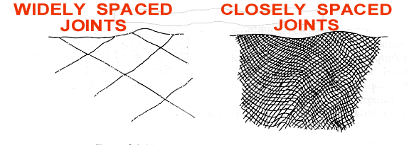
The sketch shows the extreme conditions encountered during grouting operations.
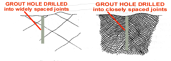
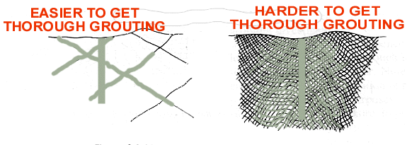
As far as cement grouting is concerned, it is the open, groutable joints that are of interest. If they are widely spaced, the grouting is usually easier than if closely spaced where troubles such as frequent surface leaks, collapsing holes and patchy penetrations can happen. These make for more expensive grouting, perhaps requiring special surface treatment.
2. Joint Widths and Continuity
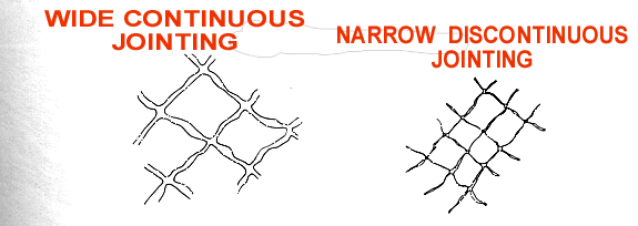
The easiest joints to grout have widths in the range between about 0.250 in [6 mm] and 0.020 in [0.5 mm].
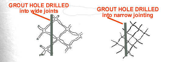
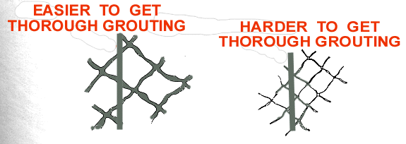
Continuity of open jointing systems affects penetration: lack of continuity means that more grout holes will be needed than if grout can travel appreciable distances through the systems.
3. Joint Inclination
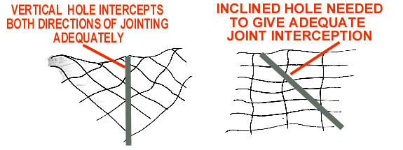
Where dipping is mainly between 20� and about 60�, vertical grout holes may give optimum interception. These are the easiest to drill and are preferable. Steeper jointing usually requires use of inclined holes.
4. Uniformity of the Site

Uniformity of jointing permits a regular layout of grout holes, whereas irregular jointing, dykes, disconformities, and so on may require placement of holes at various inclinations and spacings . Weaknesses may need to be treated intensively.
5. Rock Soundness
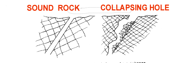
Holes that don't collapse permit easier grouting than those that do. In the latter case, packers cannot be used, and stage lengths may have to be shorter than usual if collapsed material blocks holes.
6. Strength
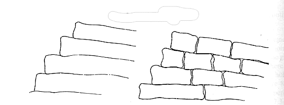
Grouting of strong, massive, well-anchored rock, as sketched at left, is usually easier than when working in weak, broken, loose materials where holes repeatedly collapse, or where blocks move as shown at right.
7. Stress in Rock

The highly cracked foundation shown at left is unlikely to carry tectonic stresses, but the massive rock sketched at right probably does. If the foundation contains tectonic stress, the grouting will need to take account of this. Early recognition of the condition is necessary.
8. Piping
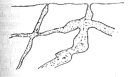
Where material in joints can be removed by seepage, either by taking the material into solution or by eroding it, the grouting will need to be more intensive than otherwise in order to ensure that seepage through such joints is virtually eliminated.
9. Chemical Attack
The presence of coal or other carbonaceous material or of other deposits that may provide chemically aggressive seepage can warrant provision of a higher standard of grouting than would otherwise be the case.
10. Karst and Other Voids
Large voids such as karst, and also old mines, shafts, and so on, require special provisions when grouted, possibly using fillers in the grout.
11. Stressed Rock
Much of the earth's surface is under stress, usually related to tectonic plate activity. The implications as far as grouting is concerned are that valleys in particular may contain rock under stress that is liable to move under the stimulus of grouting. To get a general idea of how stresses affect a valley, consider the following scenario in geological time:-
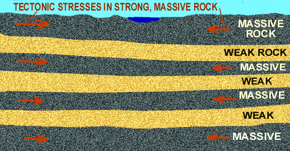
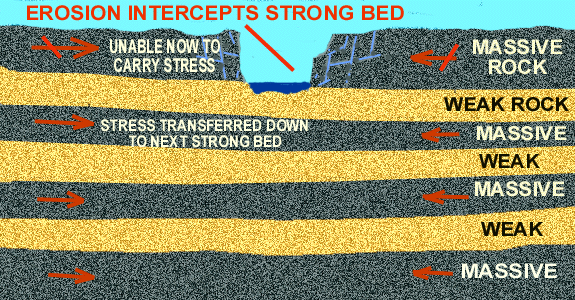
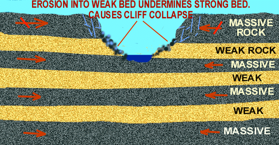
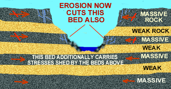
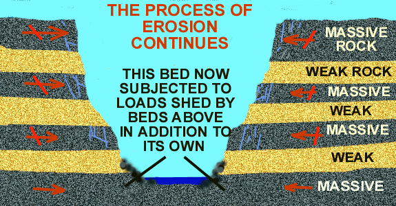
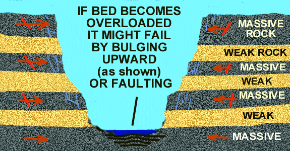
This sequence of illustrations shows the process
It shows a vertical slice through a foundation containing alternating beds of massive, strong rock and weak, easily broken material. The massive beds attract any tectonic stresses while the weak beds don't - they shatter and stress relieve themselves to throw off any horizontal forces.
A valley now starts to erode through these beds. After a while the top massive bed is cut and can no longer carry horizontal stresses across the site. Its stresses are then transferred to the next lower massive bed. This transferral takes place well back behind the valley walls, on a regional basis. However, since this lower massive bed already had stresses in it, it now has more.
When erosion eventually proceeds deeper and cuts this highly stressed massive bed its stresses are transferred in turn to the next lower massive bed, which already has its own stresses.
The addition of the stresses shed from above may be too much for it and it may fail.
This failure may take the form of valley bulging, a local anticline, a fault, or other feature.
Distortion of beds and the presence of highly weathered infill or fault gouge are the usual signs that this has happened.
There are easily recognised visual signs if stressed rock is present; they are indicated in the sketch below:-
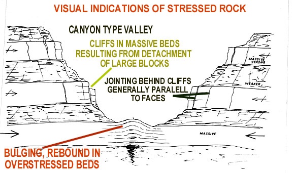
These signs are:-
- Valleys tend to be more of the canyon type rather than having gentle slopes
- The massive beds, indicated by cliff formation, have large blocks bodily detached from the main mass behind. These blocks eventually tumble to expose fresh cliff faces.
- Major open jointing, more or less parallel to cliff faces, lies behind the faces. This eventually forms the fracture planes of future detached blocks.
- The valley floor has weaknesses as earlier mentioned.
These visual signs are usually more useful than conducting stress testing and are certainly adequate for grouting purposes.
INDICATIONS WHEN DOING GROUTING
When grouting a hole, the following signs indicate that rock has probably moved:
- A sudden increase in grout take for no apparent reason
- Sudden loss of pressure in the hole.
Grout operators should watch for these signs at all times, even on sites where movement is not particularly likely, and should always start each application at low pressure.
GROUT CURTAIN DESIGN
(Some segments of an extensive subject)
Having decided on suitable hole inclinations to suit the various parts of a site, it is then necessary to merge them into an overall design. In doing this some of these carefully considered angles may have to be varied in order to produce a workable design.
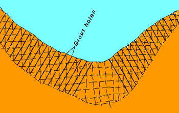
Let's start with this simple case. It is a typical dam site valley. For the purposes of the example, jointing is assumed to be approximately horizontal and vertical right across the site. On the left side, grout holes sloping into the abutment at about the inclination shown would give adequate interception of the jointing. Similarly, the same inclination in the right abutment would be satisfactory. However, the inclinations in the two abutments are in opposite directions to each other; so what should be done where they meet in the floor of the valley?
There are two options:
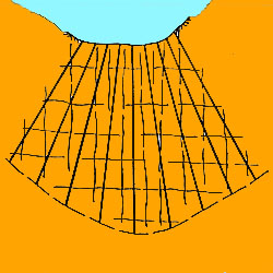
- 1. Transition smoothly from one direction to the other as shown in the sketch. Notice how poorly the vertical joints are intercepted. And these are quite liable to carry seepage through the line of the curtain if not properly grouted.
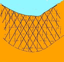
In order to check out both alternatives thoroughly, I have grouted several comparable dams using each method. Even though the transition method started with less holes than the crossover method, so many additional holes were needed to bring the standard of grouting in the vertical cracks down to an acceptable figure that the final number of holes exceeded those in the crossover method in all cases, and far more time was lost in fiddling around in confined working areas.
Another important factor favouring use of the crossover method is that it gives doubled-up treatment of geological weaknesses in the valley floor.
Nearly every valley has some weakness in its floor - that is why the valley is there - water has followed the weakness to erode the valley. This may take the form of a fault, shear zone, anticline, graben, or some other feature and presents a specific feature warranting special attention. This is best provided by the crossover layout
Of course, if unlike the previous example, the jointing is amenable to vertical holes, things are simplified in the valley floor. The vertical holes simply continue across - unless weaknesses there specifically require locally inclined holes.
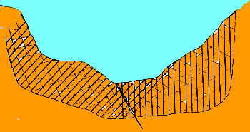
Curtains do not have to be symmetrical. If the jointing in one of the abutments is quite different to the other, hole inclinations should also differ. The sketch shows an example.
The left abutment requires fairly well angled holes, whereas vertical holes will suffice in the right. A fault separates the two and is crossed by holes from both directions in the crossover. The extreme right-hand hole of the crossover is in an awkward location for drilling; this sometimes happens on sites but might be avoided by relocating the hole and changing its angle to still provide adequate intersection in the area it deals with, which is down near the base of the curtain.
Dips on the left abutment gradually vary, but it is unwise to gradually vary hole inclinations to match (complications and inadvertent errors in hole layout can be introduced if they are). If the curtain happened to be longer than the one shown, a change to another angle for part of it would be warranted.
In this example the curtain has not been deepened in the vicinity of the fault. If water testing had found permeabilities there in excess of the adopted standard for the curtain, then deepening would indeed be needed.
The cases so far have been in valleys where sloping abutments have dictated the direction in those having sloping holes. However, alternative directions are possible if the surface is fairly level.
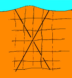
The horizontal and vertical joints shown here can be intercepted equally well by the inclined hole shown in full line or by the hole at the same angle but in opposite direction shown dashed. This concept is used in some multiple-row curtains where one row is at one of the angles and the next is at the other angle. If there are more than two rows, the alternative arrangement continues in each.
THAT COMPLETES THIS PROGRAMME
You might like to go on to the bookl Construction and Design of Cement Groutingby this author. It gives greater detail about design of grouting.
And if you have reached here without going HOME, it is suggested that a visit there can give much more interesting information about grouting.